Engineering drawing is a fundamental tool used by engineers to communicate design concepts and specifications. It provides a visual representation of an object or system, allowing for effective communication between designers, manufacturers, and users. One essential aspect of engineering drawing is the concept of a cutting plane.
In this blog post, we will explore the concept of cutting planes in engineering drawing, including what they are, how they are represented, and their significance in understanding the internal features of an object. We will also delve into various types of lines used in engineering drawing, including those associated with cutting planes, section views, and scales. So, let’s dive in and unravel the mysteries of cutting planes in engineering drawing!
What is Cutting Plane in Engineering Drawing
In the captivating world of engineering drawing, the concept of a cutting plane might sound like something out of a sci-fi movie. But fear not, dear reader, it’s not as intimidating as it may seem. So grab your pencil and let’s dive right into this fascinating topic!
A Closer Look at the Cutting Plane
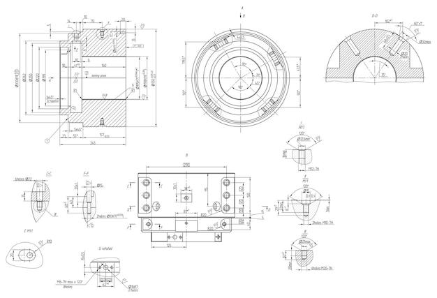
Imagine you have a complex 3D object that you want to represent on a 2D surface—an engineering drawing, for instance. But here’s the catch: this object is so intricate that representing it accurately would result in a cluttered mess of lines. This is where the cutting plane comes to the rescue!
The cutting plane is like a superhero with the power to slice through an object, revealing its inner details. It acts as an imaginary plane that intersects the object, allowing us to see what’s inside without the need for an X-ray vision. Think of it as a magician’s curtain, pulled aside to expose the hidden secrets within.
The Purpose of the Cutting Plane
Now, you might be wondering: why go to all this trouble? Well, my friend, the purpose of using a cutting plane is to provide a clear, concise representation of an object’s interior features, such as cavities, holes, or internal structures. It simplifies the drawing, making it easier to understand and interpret.
By selectively revealing the important details through the cutting plane, we can avoid overwhelming the viewer with a cluttered mess of lines. It’s like giving someone a sneak peek into the workings of a complex machine without bombarding them with an onslaught of technical jargon.
How to Use the Cutting Plane Effectively
To utilize the cutting plane effectively, engineers employ a set of internationally recognized conventions. These conventions ensure that the cutting plane symbol is correctly placed and oriented, and that it is clearly understood by all who lay eyes upon it.
One popular convention is to represent the cutting plane as a dashed line with arrows on both ends. This helps differentiate it from the regular solid lines used to represent the object itself. The cutting plane line is usually labeled with a letter, conveniently starting with “A” and progressing alphabetically if multiple cutting planes are required.
Benefits and Limitations of the Cutting Plane
Like any superhero, the cutting plane has its strengths and weaknesses. Its main benefit lies in its ability to simplify complex objects, making them easier to understand. It allows engineers to communicate their design intent clearly, ensuring that manufacturing and assembly processes go smoothly.
However, it’s important to note that the cutting plane has its limitations. It’s not a magical solution that can reveal every nook and cranny of an object. In some cases, certain details may be obscured or require additional views or sections to fully comprehend.
Let the Cutting Plane Enhance Your Engineering Drawings
Now that you have a clearer understanding of what the cutting plane is and how it works, it’s time to unleash its power in your own engineering drawings. Remember, the cutting plane is your ally in simplifying complex objects and communicating your design intent. Embrace its capabilities, and let your drawings come to life with clarity and precision!
So, dear reader, go forth and conquer the world of engineering drawing with your newfound knowledge of the cutting plane. Your designs will never be the same again!
Stay tuned for more exciting adventures in the realm of engineering drawing. Until then, happy drawing and may the cutting plane be with you!
FAQ: What Is a Cutting Plane in Engineering Drawing
In the world of engineering drawing, a cutting plane plays a crucial role in clearly depicting the internal details of objects. It helps engineers visualize and understand the inner workings of a design. In this FAQ-style section, we’ll address some common questions about cutting planes that will help demystify this important concept.
What Is a Removed Section
A removed section refers to a specific area or part of an object that has been cut and removed to expose its internal features. It allows engineers to get a clear view of the internal structure without clutter or obstructions. Think of it as peeling back the layers to reveal what’s hidden beneath.
What Are the Thin Lines Used to Indicate Where the Cutting Plane Line Has Cut Through Material
To indicate where the cutting plane line has cut through the material, engineers use thin lines called section lines. These lines are drawn parallel to the cutting plane and help distinguish between the solid material and the removed section. They essentially provide a visual clue about what has been removed from the object.
What Type of Line Is Used to Draw Cutting Planes
In engineering drawing, a specific type of line called a cutting plane line is used to represent the cutting plane. This line is typically drawn as a thick, bold line to clearly differentiate it from other types of lines in the drawing. It acts as a visual guide, indicating where the object has been cut to reveal its internal details.
How Many Types of Lines Are There in Engineering Drawing
Engineering drawing involves various types of lines, each serving a specific purpose. Some common types include the object line, hidden line, center line, dimension line, extension line, and, of course, the cutting plane line. Each line type contributes to creating a precise and comprehensive representation of the object.
How Many Cutting Plane Lines Are There
There is typically just one cutting plane line in a drawing. It represents the line along which the object has been cut to expose its interior. This line helps engineers focus their attention on the specific area of interest.
What Are the Two Types of Cutting Plane Lines
The two types of cutting plane lines used in engineering drawings are full cutting plane lines and dotted cutting plane lines. Full cutting plane lines are solid, bold lines used to represent the cutting plane when the entire length of the object is cut. On the other hand, dotted cutting plane lines consist of evenly spaced dots and are employed when only a portion of the object is cut.
What Is a Section Line in Drawing
A section line is a thin, parallel line used to indicate where the cutting plane has intersected the object. It helps distinguish between the solid material and the removed section, providing clarity and understanding of the object’s internal features. Section lines are positioned perpendicular to the cutting plane line.
What Are 5 Types of Lines
Engineering drawing incorporates various line types to convey specific information. Here are five common types of lines:
1. Object lines: Clearly define the outline of the object.
2. Hidden lines: Represent features not visible from the current viewpoint.
3. Center lines: Indicate the center or axis of a symmetrical object.
4. Dimension lines: Display the measurements and dimensions of the object.
5. Cutting plane lines: Show where the object has been cut to reveal internal details.
What Is Called a Cutting Plane
A cutting plane is an imaginary plane that cuts through an object to expose its internal features. By using the cutting plane, engineers can study the object’s inner workings without the need for physical disassembly. It’s like having x-ray vision for industrial design!
What Are the Types of Cutting Planes
In engineering drawing, there are two main types of cutting planes: full cutting planes and half cutting planes. Full cutting planes cut an object entirely, while half cutting planes only reveal a section of the object. Whether you want the full picture or just a sneak peek, cutting planes have got you covered!
What Is a Viewing Plane Line
A viewing plane line is not specifically related to cutting planes, but it’s worth mentioning. This line represents the outline of the plane or surface from which the object is being viewed. It helps establish the viewing perspective and provides a frame of reference for understanding the object in context.
What Is a Short Break Line
A short break line is a jagged line used to indicate that a portion of the object is intentionally omitted for clarity purposes. It signifies that the complete object continues beyond what is shown and avoids unnecessary repetition in the drawing. Unlike a break-up line after a rough breakup, a short break line keeps things concise and clutter-free!
How Are Cutting Planes Represented
Cutting planes are represented by thick, bold lines that extend across the object, indicating the location and direction of the cut. Additionally, section lines are used parallel to the cutting plane line to show where the cut has penetrated the object. Together, they create a clear visual representation of the internal details of the object.
What Is the Cutting Plane Line Used For, and How Does It Look
The cutting plane line serves the purpose of visually showing where an object has been cut to reveal its internal features. It appears as a bold, thick line, usually heavier than other lines in the drawing to ensure clear visibility. By following the cutting plane line, engineers can mentally dissect the object and explore its concealed intricacies.
What Are the 7 Types of Section Views
Section views are incredibly useful in engineering drawing to reveal internal details. Here are seven common types of section views:
1. Full section view
2. Half section view
3. Offset section view
4. Revolved section view
5. Removed section view
6. Broken-out section view
7. Aligned section view
Which of the Following Represents Reducing Scale
A reducing scale is commonly represented as a ratio such as 1:2 or 1/2. It indicates that the drawing is proportionally smaller than the actual object. So, think of reducing scales as the Shrink Ray of engineering drawing—making things smaller but still packed with all the necessary details!
What Happens When the Cutting Plane Line Passes Through an Object
When the cutting plane line passes through an object, it creates a removed section that exposes the object’s internal details. This section helps engineers visualize and understand the object’s hidden features without physically dissecting it. It’s like peering inside a magical box without opening it!
How Many Types of Scales Are There in Engineering Drawing
In engineering drawing, there are various types of scales used to represent objects with different levels of detail. Common types include full-scale, large-scale, and small-scale representations. So, whether you want to go big or go small, there’s a scale for every engineering drawing need!
When Is a Pyramid or Cone Cut by a Plane
A pyramid or cone is cut by a plane when the cutting plane is parallel to its base. This kind of cut results in a section view that exposes the pyramid or cone’s internal structure. It’s like revealing the hidden geometry of ancient Egyptian pyramids in a modern engineering drawing!
What Is the Function of a Cutting Plane Line
The function of a cutting plane line, my eager friend, is to cut through the object in the drawing. By doing so, it visually exposes the internal features, allowing engineers to analyze and understand the object’s hidden intricacies. It’s like putting on a pair of X-ray glasses, but for engineers!
When Is an Object Cut by a Section Plane
An object is cut by a section plane to reveal its internal details when engineers need to understand its hidden features or structural composition. This technique allows for precise analysis without the need for physical disassembly. So, consider section planes as the superhero cape of engineering drawing—they unveil the object’s superpowers!
Now that your burning questions about cutting planes in engineering drawing have been answered, you’re ready to delve even deeper into the fascinating world of technical design. Get your pencils and rulers ready because endless possibilities await!