Welcome to our beginner-friendly guide on how to make a simple series circuit! If you’ve ever wondered how electricity flows through a circuit or wanted to try building one yourself, you’ve come to the right place. In this blog post, we’ll walk you through the step-by-step process of creating a basic series circuit and answer some common questions along the way.
Whether you’re a curious student, a DIY enthusiast, or just someone interested in understanding the fundamentals of circuits, this guide will provide you with all the information you need. We’ll explain the difference between a simple circuit and a series circuit, introduce you to the essential components you’ll need, and even touch on the intriguing world of printed circuit boards (PCBs).
So, let’s roll up our sleeves and dive into the fascinating world of circuits as we explore how to make a simple series circuit together!
How to Make a Simple Series Circuit
Understanding the Basics
Before we dive into the nitty-gritty of making a simple series circuit, let’s brush up on the basics. A circuit is like the circulatory system of electronics, allowing electricity to flow from one point to another. In a series circuit, the components are connected one after another, creating a single path for the current to follow.
Gather Your Tools
To create your own simple series circuit, you’ll need a few basic tools and components. Don’t worry; you won’t need a fancy toolkit or an electrical engineering degree. Here’s what you’ll need:
- Breadboard: Think of it as your circuit’s playground. A breadboard is a handy platform to connect your electrical components without the need for soldering.
- Wires: These are the highways that conduct electricity. Get yourself some jumper wires, preferably with different colors, to make it easier to keep track of the connections.
- Resistors: These little fellas limit the flow of electric current. It’s like a traffic cop who maintains order in the circuit. Make sure to have a few different resistors on hand with varying resistance values.
Let’s Get Building
- Step 1: Safety First: Before working on any circuit, it’s essential to prioritize safety. Make sure your workspace is clean, tidy, and free from any water or potential hazards.
- Step 2: Plan Your Circuit: Take a moment to sketch out your circuit design on paper. It will help you visualize the connections, identify potential problems, and make the actual building process smoother.
- Step 3: Place the Components: Begin by placing your resistors on the breadboard. You’ll notice two rows of holes connected with a metal strip running beneath them. Insert the resistors, ensuring one lead is connected to one row and the other lead to the adjacent row.
- Step 4: Connect the Wires: Now it’s time to add the wires to complete the circuit. Use your jumper wires to connect one end of the first resistor to the positive rail of the breadboard (marked with a red line or a plus sign).
- Step 5: Add the Power Source: Attach one end of another jumper wire to the negative rail of the breadboard (marked with a blue line or a minus sign). This will serve as your circuit’s power source.
- Step 6: Loop It Around: Finally, take the free end of your second jumper wire and connect it to the other end of the first resistor. Congratulations! You’ve successfully built a simple series circuit.
Testing, Testing, 1-2-3
Now that your circuit is ready, it’s time for the moment of truth – testing it out. Safely plug in your power source, whether it’s a battery or a DC power supply, and observe the flow of electricity. If everything is connected correctly, your circuit should come to life, and current should flow smoothly through the resistors.
Troubleshooting Tips
If your circuit isn’t working as expected, don’t panic! Here are a few troubleshooting tips to help you out:
- Double-check your connections: One loose wire can disrupt the entire circuit.
- Verify resistor values: Ensure you’re using the right resistors for your circuit’s needs.
- Watch out for short circuits: Avoid accidentally connecting your circuits with jumper wires.
- Check your power source: Ensure the battery or power supply is supplying the correct voltage.
Making a simple series circuit doesn’t have to be intimidating. With a breadboard, wires, and resistors, you can create your own custom circuit and explore the world of electronics. Have fun, don’t be afraid to experiment, and remember, even if things don’t work out the first time, debugging is just part of the process. Happy circuit building!
Frequently Asked Questions – How to Make a Simple Series Circuit
How Does a Simple Circuit Work
A simple circuit works by creating a continuous loop for electricity to flow. It consists of three basic elements: a power source, such as a battery, wires to connect the components, and a load, which can be a light bulb or any other device that uses electricity. When the circuit is complete, the power source provides electrons that flow through the wires, energizing the load and causing it to function.
What Is the Difference Between a Simple Circuit and a Series Circuit
In a simple circuit, there is only one path for the electric current to flow. On the other hand, a series circuit is a specific type of simple circuit where the components are connected in a chain. In a series circuit, the current flows through each component in sequence, meaning that if one component fails, the entire circuit will be interrupted, and all components will stop working.
What Is a Series Circuit KS3
In KS3 (Key Stage 3) science, series circuits are explored as part of the curriculum. A series circuit is a basic electrical circuit where the components are connected in a single loop. It helps students understand how electricity flows through a circuit and the effects of adding or removing components on the overall operation of the circuit.
How Do You Make a Circuit Without Wires
While wires are commonly used to connect components in a circuit, it is also possible to create a circuit without wires. This is known as a wireless circuit or a wireless power transfer system. These circuits use techniques such as electromagnetic induction or radio frequency transmission to deliver power to devices without the need for physical connections. Wireless circuits are often used in applications like wireless charging pads or remote control systems.
Can You Make Your Own PCB
Yes, you can make your own PCB (Printed Circuit Board). PCBs are used to mechanically support and electrically connect electronic components using conductive tracks, pads, and other features. To make your own PCB, you would typically need specialized equipment like a PCB etching kit, copper-clad boards, and chemical solutions. However, with advancements in technology, there are now online platforms available that allow you to design and order custom PCBs without the need for physical manufacturing.
What Are the Five Basic Circuit Elements
The five basic circuit elements are resistance, capacitance, inductance, voltage sources, and current sources. Each element plays a crucial role in determining the behavior of a circuit. Resistance controls the flow of current, capacitance stores electrical energy, inductance resists changes in current flow and voltage sources provide electrical potential, while current sources supply a constant flow of current.
Why Is PCB Green
PCBs are often green due to the solder mask applied to the circuit boards. The green color is the most commonly used solder mask color for PCBs, but it is not mandatory. Other colors like red, blue, white, or even black can also be used. The solder mask is applied to protect the copper traces on the PCB from oxidation, solder bridging during assembly, and to insulate different conductive paths from each other.
What Are the Four Basic Components of a Circuit
The four basic components of a circuit are resistors, capacitors, inductors, and diodes. Resistors limit the flow of current, capacitors store electrical charge, inductors resist changes in current, and diodes control the direction of current flow. These components can be combined in various ways to create more complex circuits that perform specific functions.
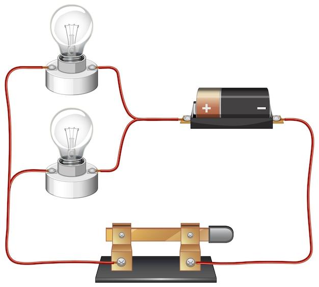
What Is a Series Circuit with Diagram
A series circuit is a circuit where the components are connected in a single loop, one after another, creating a chain-like structure. In a series circuit diagram, the components are represented by their respective symbols, and the connections between them are shown as continuous lines. A series circuit diagram is a visual representation that helps illustrate how the components are interconnected and the flow of current through the circuit.
What Are Examples of Simple Circuits
Examples of simple circuits include a flashlight circuit, a doorbell circuit, or a basic LED circuit. In a flashlight circuit, a battery acts as the power source, and wires connect the battery to a switch and a light bulb. When the switch is turned on, the circuit is complete, and the light bulb illuminates. Similarly, a doorbell circuit includes a power source, wires, a switch, and a buzzer or chime that produces the sound when someone presses the doorbell button.
How Can I Create PCB Online
Creating PCBs online has become much more accessible with the availability of various online platforms. These platforms allow you to design your PCB using user-friendly software tools. You can define the dimensions, layout, and components of your circuit, and the online platform will generate the necessary files for manufacturing. This simplifies the process of creating custom PCBs, especially for hobbyists or smaller-scale projects.
How Do You Make a Simple Circuit for Kids
Making a simple circuit for kids can be a fun and educational activity. Here’s a step-by-step guide to creating a simple circuit:
-
Gather materials: You will need a battery, a small light bulb, some wires with alligator clips, and a switch (optional).
-
Connect the components: Attach one end of a wire to the battery’s positive terminal and the other end to one side of the light bulb. Then, connect another wire from the other side of the light bulb to the battery’s negative terminal.
-
Add a switch (optional): To control the flow of electricity, you can add a switch between one of the wires. This allows you to turn the circuit on or off.
-
Test the circuit: Once everything is connected, turn on the switch or touch the loose ends of the wire together. The light bulb should light up, indicating that the circuit is working.
Why Is Parallel Better Than Series
In general, a parallel circuit is often considered better than a series circuit for certain applications. Here are a few reasons why parallel circuits are preferred:
-
Redundancy: In a parallel circuit, if one component fails, the other components can still function independently. This increases reliability and ensures that a single failure does not disrupt the entire circuit.
-
Voltage distribution: In a series circuit, the same current flows through each component, but the voltage is divided among them. In a parallel circuit, each component receives the full voltage, which can be advantageous for devices that require a specific voltage to operate optimally.
-
Independent operation: Components in a parallel circuit can work independently of each other. This is useful when you want to control each component individually or have different components with varying power requirements.
How Do You Know if a Circuit Is Series or Parallel
To determine whether a circuit is series or parallel, you can observe the wiring arrangement of the components. In a series circuit, the components are connected end-to-end, forming a single continuous loop. In a parallel circuit, the components are connected side-by-side, offering multiple paths for current to flow. By tracing the connections and identifying the arrangement, you can determine whether the circuit is series or parallel.
What Are the Three Types of Circuits
The three types of circuits are series circuits, parallel circuits, and series-parallel circuits.
-
Series circuits: In a series circuit, the components are connected in a single loop, with the same current flowing through each component. If one component fails, the entire circuit will be interrupted.
-
Parallel circuits: In a parallel circuit, the components are connected side-by-side, providing multiple paths for current to flow. Each component receives the full voltage, and if one component fails, the others can continue to function.
-
Series-parallel circuits: Series-parallel circuits combine elements of series and parallel circuits. They feature both series-connected components and parallel-connected components, offering a balance between the advantages of series and parallel arrangements.
What Is a Simple Series Circuit
A simple series circuit is a basic electrical circuit where the components are connected in a single loop, one after another, like a chain. In a simple series circuit, the same current flows through each component in sequence. This allows for easy control and understanding of the circuit’s behavior. However, it also means that if one component fails or is removed, the entire circuit will be affected.
What Are the Three Requirements of a Circuit
For a circuit to function properly, three requirements must be met:
-
A power source: The circuit needs a source of electrical energy, such as a battery or power supply, to provide the necessary potential difference for the flow of current.
-
Closed loop: The circuit should have a complete, unbroken path for the current to flow through. This is typically achieved by connecting the components using conductive materials like wires.
-
Load: The circuit must have a load, which is a device or component that uses the electrical energy from the power source. This can be a light bulb, a motor, a resistor, or any other electrical device.
How Do You Make a Series Circuit with a Light Bulb
To make a series circuit with a light bulb, follow these steps:
-
Gather materials: You will need a battery, a light bulb, and some wires.
-
Connect the battery: Attach one end of a wire to the positive terminal of the battery and the other end to one terminal of the light bulb.
-
Complete the circuit: Connect another wire from the other terminal of the light bulb to the negative terminal of the battery.
-
Test the circuit: Once everything is connected, the light bulb should illuminate when the circuit is complete. If it doesn’t light up, check the connections and make sure the battery is not dead.
How Do You Make a Simple Circuit Step by Step
Here’s a step-by-step guide to making a simple circuit:
-
Gather materials: You will need a battery, a light bulb, some wires, and a switch (optional).
-
Connect the components: Attach one end of a wire to the positive terminal of the battery and the other end to one terminal of the light bulb. Then, connect another wire from the other terminal of the light bulb to the negative terminal of the battery. If desired, add a switch between one of the wires to control the flow of electricity.
-
Test the circuit: Once everything is connected, turn on the switch or touch the loose ends of the wire together (if there is no switch). The light bulb should light up, indicating that the circuit is functioning correctly.
Do Circuits Need a Light Bulb to Work
No, circuits do not necessarily require a light bulb to work. A light bulb is just one example of a load or device that uses electrical energy. Circuits can be designed to power a wide range of devices, such as motors, speakers, sensors, or even complex electronic systems. The essential requirement is that the circuit provides a complete path for the flow of current, and there is a load that utilizes the electrical energy provided by the power source.
What Two Things Does Every Circuit Have
Every circuit has two essential components:
-
Power source: A circuit needs a power source to provide the electrical energy necessary for the flow of current. This can be a battery, a generator, a solar panel, or any other device that produces a potential difference.
-
Closed loop: A circuit must have a closed loop or a complete path for the current to flow through. This is typically achieved by connecting the components using conductive materials like wires. The closed loop allows the current to flow from the power source, through the components, and back to the power source, completing the circuit.
What Materials Do You Need to Make a Simple Circuit
To make a simple circuit, you will need the following materials:
-
Battery: This serves as the power source and provides the electrical energy needed for the circuit to work. Choose a battery with the appropriate voltage and size for your circuit.
-
Light bulb: A light bulb is a common component used in simple circuits to demonstrate the flow of electricity. Select a light bulb that matches the voltage of your battery.
-
Wires: Wires are used to connect the components together and create a complete path for the current to flow. They should have conductive cores, such as copper or aluminum, which allow for the easy flow of electricity.
-
Switch (optional): A switch allows you to control the flow of current in the circuit. It can be used to turn the circuit on or off. If desired, include a switch in your circuit design.
What Is an Ideal Basic Circuit Element
In the field of electrical engineering, an ideal basic circuit element refers to a theoretical component that exhibits specific electrical characteristics without any internal resistance or unwanted parameters. These elements are often used as building blocks in circuit analysis and design. Examples of ideal basic circuit elements include ideal resistors, ideal capacitors, ideal inductors, ideal voltage sources, and ideal current sources. While no real component is entirely ideal, these theoretical elements provide a simplified model for analyzing and understanding the behavior of electrical circuits.